Industry News, trenchless projects
The following is a post from Akkerman. For more details and additional job site photos, visit their website.
 BRH-Garver Construction LP, a Houston based civil construction contractor pipe jacked 885-linear feet of 66-inch ID Permalok® casing filled with 48-inch carrier lines to convey treated water from the Canal Water Treatment Plant (WTP) for El Paso Water in El Paso, TX. The project risks and rewards existed in equal measure for all stakeholders.
The Canal WTP, also known as the Robertson Umbenhauer, was constructed 75-years ago and is situated between the Rio Grande River and a 100-year old BNSF rail yard. The new transmission lines culminate to tie in at San Antonio Avenue in downtown El Paso.
The water lines on the Canal Water Treatment Plant Discharge Main Tunnel project traveled under Highway I-85, and 18 BNSF rail yard tracks in soft ground conditions presenting many opportunities for settlement. El Paso’s water table is prone to seasonal variability due to its proximity to the river, and the likelihood of contaminated ground, existing utilities and obstructions in the 100-year old rail yard posed a potential threat to tunneling personnel and loss of production. Since the launch shaft was in an active BNSF rail yard, frequent and diligent communication and coordination with the railroad personnel transpired for safety, and equipment and material staging.
Several factors contributed to project cost savings including the use of a more cost-effective Tunnel Boring Machine (TBM) system over a microtunneling system, a value-engineered design to initiate both bores from one launch shaft inside the rail yard to emerge into one reception shaft, the downsizing of casing diameter from 72 to 66-inch, and the avoidance of deep well dewatering, which also reduced settlement risk.
The contractor’s pipe jacking experience informed the resolution of the project’s more difficult challenges when completing the 570- and 315-linear foot tunnels. When unforeseen cobbles were discovered, the hydraulic doors on the TBM cutter head provided passage for the cobbles with minimal loss of production. When unpredicted boulders were discovered, although (continued)tunneling had to pause to allow chemical grout to be used to stabilize the bore, the hydraulic doors provided essential access for breaking the boulders to a size that allowed for their passage to successfully complete the tunnel. When the crew ran into unanticipated PPCA ground conditions, the crew persevered by using a full-face mask filtration system to resume mining operations.
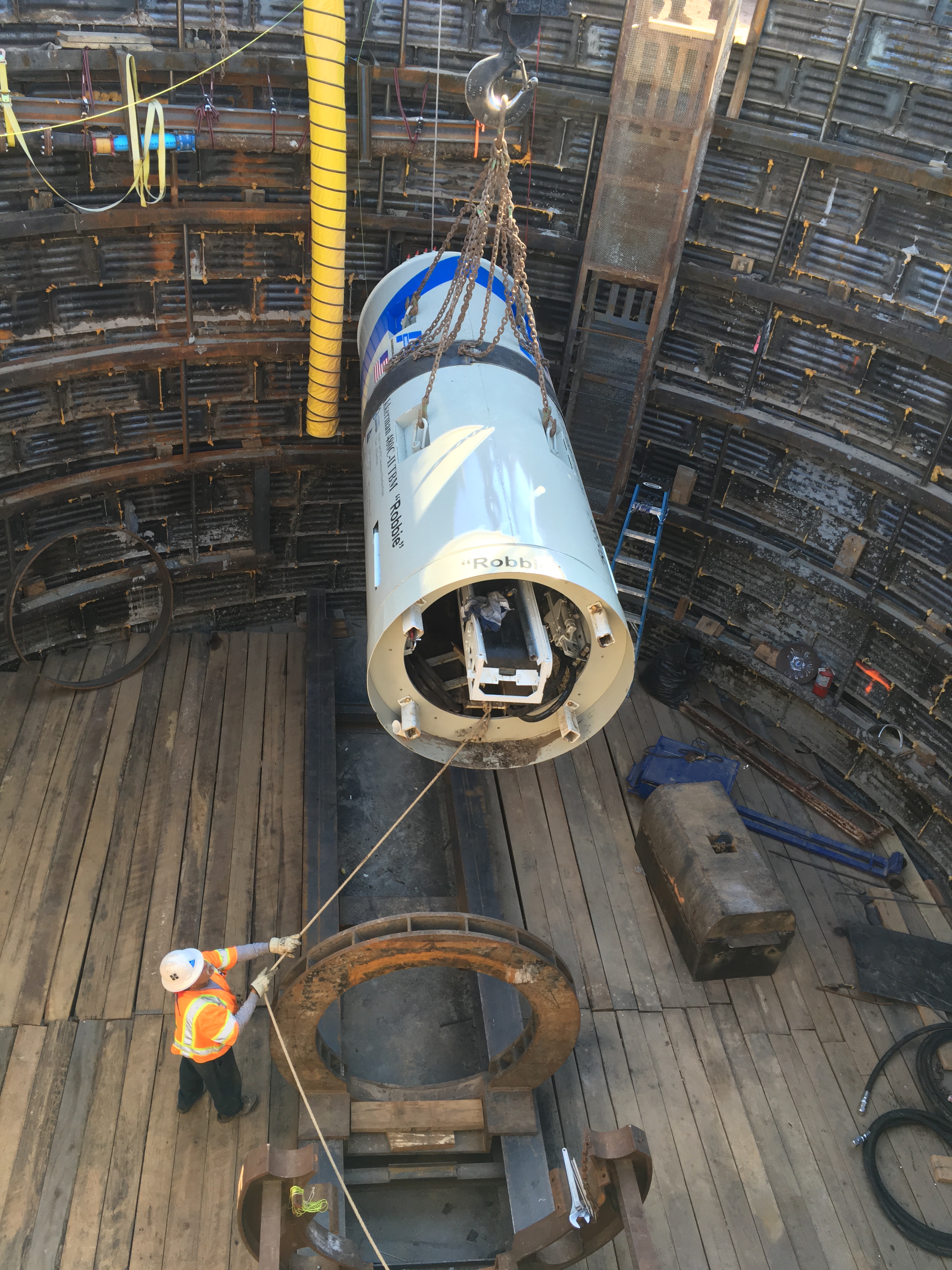
The project was deemed successful, and the TBM named “Robbie” in honor of the 75th anniversary of the Robertson Umbenhauer WTP, proved to be the right method.
- Breff Cooling of BRH Garver, comments on the equipment selection, “The versatility of the Akkerman TBM with hydraulically-operated doors, gave us some options that a MTBM would not have. A slurry machine may have been the preferred choice under critically located structures in ground that varies from clay, to sand seams, to running gravels. However, the small but real possibility of boulders, or steel fish plates and other obstructing debris sometimes found under rail yards, tipped the balance towards selecting a manned-entry TBM for accessing any obstructions. With the benefit of hindsight, we can say that the TBM turned out to be the better choice in this case because we ended up discovering unforeseen boulders.”
Cooling also credits the railway stating, “We are grateful for the exceptional cooperation from BNSF for accommodating our field operations inside their busy 24-hour around-the-clock rail yard operations.”
The Canal Water Treatment Plant Discharge Main Tunnel project was designed by a partnership between CDM Smith and Parkhill, Smith & Cooper who also provided site supervision and contract administration. Tunneling technical support, oversight and settlement monitoring was performed by Killduff Underground Engineering.
Cooling concludes, “This is the third time BRH-Garver has partnered with an engineering firm for a design-build project, and the first for time for a tunneling project. The partnership accepted transfer of nearly all risk for the client and proved very effective for BRH to apply three decades of tunneling experience towards the optimum tunneling solution for the design changes. Our preference would be for this type of project delivery all of the time.”
Industry News, trenchless people, trenchless projects
When contractors provide estimates that include a sewer bypass, accuracy is essential—each project is unique, and accounting for these nuances is critical to maintaining margins. Failure to plan on the front end may lead to an influx of change orders and a big hit to the bottom line. Damages could go further than money alone: An estimating mistake might lead to a sanitary sewer overflow (SSO). Following an SSO, you can expect large sums for cleanup and DEQ penalties, along with negative PR and a ripple effect that could impact future projects.
Before submitting a bid, it’s critical to cover all the bases and avert potential problems on the job. The following lessons learned can help contractors avoid estimating mistakes, win bids, and complete projects at a profit—and without visits from the DEQ.
Lesson 1: Take a bottom-up approach to estimating.
Often estimators have little choice but to use unit costs, like cost per foot of pipe, for an estimate. But that doesn’t eliminate the need to check the latest prices. Inserting the cost from the last project without checking it seldom produces a safe number. Even if a job appears to be the same size and complexity as a previous project, treat every job individually and get a current price for every item.
Lesson 2: Always visit the project site with a knowledgeable individual.
Unforeseen site conditions are the largest contributor to project change orders and increased costs. Plans and drawings alone do not provide the information needed to route pipe, situate pumps, and manage flow for a sewer bypass. Avoiding this mistake is easy: Always visit the site with the engineer or a representative from the municipality—whoever has the most in-depth knowledge of the project. The sewer bypass subcontractor should also attend to explain the capabilities, as well as the limitations, of the pumping system. Consulting with the entire team will help ensure a solid quote for that portion of the contract.
Lesson 3: Insist on backup detail for subcontractor quotes.
Contracting firms often use subcontractors to design a sewer bypass for a larger project. Even if the subcontractor has complete confidence in the system as designed, never take their word that it will handle the sewer bypass flow for the cost they plan to charge. Instead, request the engineering calculations and system drawings, and then ask the design engineer to review them. Based on the information the subcontractor provides, the scope of equipment, system layout, and performance should be clear.
Lesson 4: Do due diligence on labor costs.
Labor costs often comprise the largest portion of a sewer bypass budget. Costs for prevailing wage and certified payroll add up quickly. Different project conditions can impact labor costs significantly, even for the same task. For example, a team working on a city street with heavy traffic may install less bypass piping each day than one working in an open field. Therefore, it’s critical to examine labor costs in detail over the project timeline, including hours and types of labor for each task. Then, make sure your bypass subcontractor offers a firm commitment on the cost.
Lesson 5: Factor in risk and the potential for lost revenue when accepting a low bid.
Although selecting the subcontractor with the lowest bid can be tempting, ultimately the project may cost more. Never assume a subcontractor will take responsibility for problems that result from lack of experience or expertise. Instead, consider all the worst-case scenarios that could occur, such as a sanitary sewer overflow. Ensure the subcontractor can manage each and every problem that may arise. Double check contract limitations and exclusions, the safety plan, and the spill and emergency response plan. In addition to liability considerations, it’s critical to review a bypass subcontractor’s bid to ensure it is complete. Have they included enough in labor costs to complete the project? Are fuel costs included, or even tax? Low bids may leave out these important components which can result in lost profits.
Lesson 6: Review the engineering submittal with the subcontractor.
To ensure all the estimate information is correct, always review the engineering submittal against the specifications with the subcontractor to make sure it matches the information in the request for quote. As a best practice, the engineering submittal should include not only the information required within the specifications, but also all the pertinent details about the temporary pumping system. It should be clear and concise so anyone who reads it will fully understand how the system is designed, set up, and operated. It should also have all the supporting documentation such as fluid calculations, drawings, and specification sheets on the equipment being used.
Checking the engineering submittal against the specifications will help to reduce or eliminate the engineer sending the submittal back for changes. Until the submittal is approved, the job cannot go forward, so in order to keep the project on track, it’s important to cross-check the documents before sending to the engineer.
Lesson 7: Assume the cost quoted can never be modified.
Do not count on subcontractors to take responsibility for problems and resolve them in a timely manner. The contractor is ultimately on the line and will be held to the amount put in every box on every bid. To be competitive, a firm’s margins must remain as low as possible while still providing a profit. If a quote does not include every item down to the last fitting and bolt, the margin and profit will suffer. The bypass subcontractor and firm should work together to determine the right costs to put into the bid tabulation sheet. Also, to avoid being buried in unanticipated invoices, be certain to incorporate a billing schedule with the bypass subcontractor that indicates when invoices will be received and what they are for.
Abiding by these seven lessons learned should avert many potential problems that occur in sewer bypass and ensure a winning bid that leads to a profitable and successful project.
For more information, visit www.sunbeltrentals.com or call 800-736-2504.
Blog, Industry News, trenchless projects
Compact TBM bores longest Rock Tunnel at 2.46 m Diameter
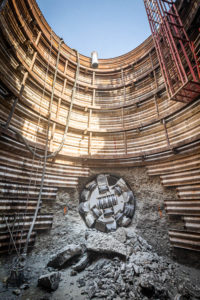 In August 2019, a small diameter Double Shield TBM made a big impact. The 2.46 m (8.07 ft) diameter Robbins machine completed 3,475 m (11,400 ft) of boring with no intermediate access, making it the longest rock tunnel ever bored by a Double Shield TBM under 2.5 m (8.2 ft) in diameter.
The machine completed the Parmer Lane Wastewater Interceptor in Austin, Texas, USA for contractor S.J. Louis Construction. Despite obstacles including two tight curves of 150 m (500 ft) radius and unexpected ground conditions that required modification of the cutterhead in the tunnel, advance rates were good. The machine reached up to 380 m (1,250 ft) per month while mining in single 12-hour shifts per day. “It was a hard rock TBM, and it performed better than expected through hard rock,” said Zach West, Project Manager for S.J. Louis.
The challenges for the TBM and its crew were varied, explained West. “The pairing of this tunnel length, which is on the longer side, and the diameter, which is on the smaller side, is challenging. The survey in a small tunnel with tight radius curves and limited surface access for over two miles is very difficult.” He added that the shallow tunnel depth, and the alignment to within a few feet of sanitary lines, high-pressure gas mains, and fuel tanks for gas stations, made TBM guidance critical. “I would say that I am most proud of our ability to guide the machine successfully through these obstacles and into our retrieval shaft within our expected tolerances.”
 Through one stretch, the tunnel advanced directly between a 30 cm (12 in) diameter, high-pressure gas main and fuel tanks for a gas station with limited as-built information. “Navigating this section took a great deal of coordination with the local utility companies. Because the tunnel diameter was too small for an automated guidance system, we manually surveyed the front of the machine at every push to ensure the machine was on track,” said West.
“I’m proud that they mined the longest tunnel to date for a small shielded gripper machine of this size without any safety issues. Kudos to their management philosophy and jobsite team,” said Tom Fuerst, Robbins Utility Tunneling Sales Manager. Robbins assisted the crew while in the tight 150 m (500 ft) curves and helped with modifications required to the cutterhead and disc cutter arrangement.
 The tunnel is located in an environmentally sensitive aquifer, with ground conditions ranging from soft dolomite with clay to limestone from 13 to 68 MPa (2,000 to 10,000 psi) UCS. “While we tunneled through the softer material, our best advance rate was close to 0.9 m (3 ft) per hour. When we tunneled through the expected limestone, advance rates were over 5.2 m (17 ft) per hour. Our best day was 25 m (81 ft) in a single shift,” said West.
The majority of the tunnel used a simple two-rock-bolt pattern for support. In the last 10% of the tunnel, ribs and lagging were used as support. Final carrier pipe, which is now being installed, consists of 110 cm (42 in) diameter fiberglass pipe.
The successful project is part of a larger trend towards small diameter, TBM-driven rock tunnels in the United States, says Fuerst. “It is primarily due to demographics and business growth. The parts of the USA that are growing need to build out their sewer and water infrastructure. TBMs can mine long distances with tight curves. They can reduce the need for multiple shafts, which lowers the overall project cost. And, given that most small diameter pipelines follow a road or municipal right-of-way, traffic problems are reduced significantly compared with open cut operations.”
 The Parmer Lane Wastewater Interceptor connects to two existing lift stations at Lake Creek and Rattan Creek. The tunnel allows for these lift stations to be decommissioned, and will provide additional flow capacity by gravity, reducing operating costs for the City of Austin.
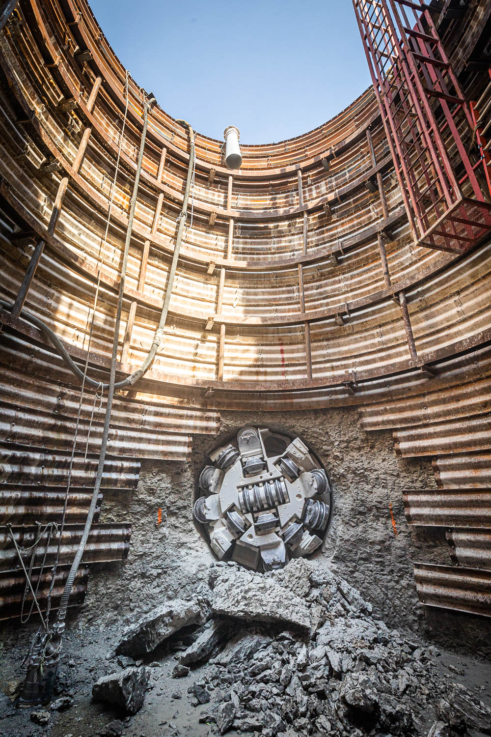
Image 1: Completed in August 2019 with a Robbins Double Shield TBM, the Parmer Lane Wastewater Interceptor will provide additional flow capacity via gravity in Austin, Texas, USA.
Image 2: The 3,475 m (11,400 ft) tunnel bored by a Robbins TBM is the longest ever bored by a Double Shield machine under 2.5 m (8.2 ft) in diameter.
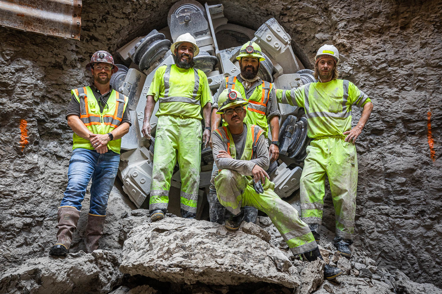
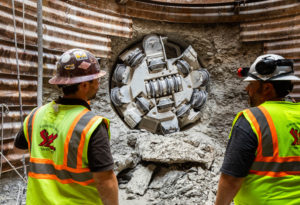
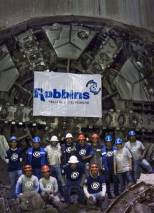
Image 3: The S.J. Louis Construction crew celebrate the successful and safe completion of the Parmer Lane Wastewater Interceptor with a Robbins TBM.
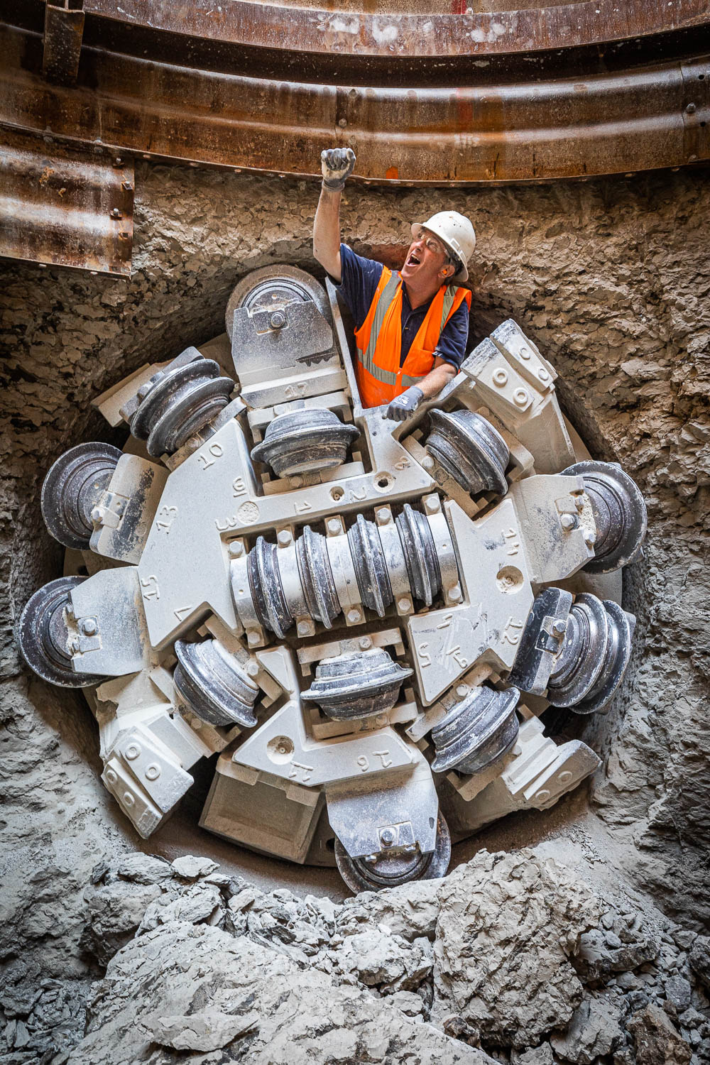
Image 4: Tom Fuerst, Robbins Utility Tunneling Sales Manager, celebrates as he exits the TBM during its August 2019 breakthrough in Austin, Texas, USA.
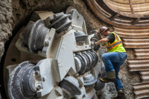
Image 5: The Robbins TBM bored through dolomite with clay and limestone at rates of up to 380 m (1,250 ft) in one month while mining in single 12-hour shifts per day.
trenchless people, trenchless projects
When a municipality puts out an RFQ for an engineering project and includes the following words—design a temporary sanitary sewer bypass system as needed to construct improvements—design engineers need to focus on two tasks: defining the scope and designing the solution. But typically, sewer bypass is just one part of a much larger project, and often design engineers aren’t trained in sewer bypass design. Fortunately, you can ask for help from bypass subcontractors and rental companies. That way, when your engineering firm helps the municipality take the project out for bid, estimators will be working with solid information that will help ensure reasonable bids.
The goal is to scope and design quickly, accurately, and effectively to avoid expensive mistakes and delays. Read on for a how-to guide to help you get it right.
Define the Scope
Before listing the steps to define the scope, let’s define what project scope actually means.
Projects are time-constrained undertakings to produce a product, service, or result. The scope defines the purpose, the ultimate goal, and how you will achieve it. Scope also determines the boundaries—what’s included in the project and what’s not. If you fail to define scope adequately, your project will likely end up over budget and behind schedule.
According to the Project Management Institute, scope changes are the single biggest reason projects fail. If the scope becomes a moving target, you’re increasing the chance for the project and your career to take a nosedive.
Here are six steps to help you thoroughly define the project scope.
- Provide an overall project description. The project description should include what the municipality wants to accomplish, the current sewer capacity, equipment in use, location and layout of existing facilities, and duration of the project. You may also want to note challenges, such as existing buildings, roads, and other structures, or areas of environmental concern such as creek crossings.
- Explain the driving forces. Billions of dollars in federal aid have been made available to rehabilitate decaying sewer systems. Many municipalities have taken advantage of the funds to initiate rehabilitation projects, whether for sewer lines, lift stations, or wastewater treatment plants. Or the municipality may be working under a consent decree that mandates specific improvements to a sewer system by a deadline.
- Specify the deliverables. The municipality’s requirements may list the details of sewer system improvements. But often the sewer bypass system itself simply directs you to design a system that will allow the improvements to be made without an interruption of service. It’s up to you to determine the requirements and provide the specifications.
- Determine the boundaries. Based on the improvements the municipality intends to make, you’ll need to determine exactly what the sanitary sewer bypass system should look like to meet the sewer requirements for as long as the project is active. For example, you’ll need to determine if the temporary system must operate at all times during construction, if it can be tied into the existing sanitary sewer system overnight, if the existing sanitary sewer system can be returned to normal flow for long periods, and if the flow can be partially diverted or must be fully diverted.
- State your assumptions. Define the conditions you’re assuming and their impact on the project. For example, the municipality may claim sandy soil in an area. If it’s actually rocky, you’ll be less productive while dealing with unexpected soil conditions. That will impact project time and cost, and generate a change order.
- List uncertainties and potential impacts. Uncertainties create risk and cost money. For example, you need to know up front of any time limitations on when work can be performed to complete the project. You also need to be aware of physical obstructions such as rivers and streams, railroad crossings, parks, and public and private property the sewer bypass may need to cross.
Design the Solution
Your bypass system design needs to be as detailed as possible, or you risk change orders, higher costs, and a damaged reputation. You may want to rely on a bypass subcontractor and/or rental company to help you specify accurately. In addition, technology continues to evolve, and the design should allow the project to meet the highest standards at the lowest cost in the shortest amount of time.
If you’ve established a partnership with a company with expertise in designing sewer bypass systems, you’re a step ahead. You can provide the known parameters to the bypass subcontractor or pump rental company and receive a sewer bypass design in return. For parameters that the municipality can’t provide, your partner can go on site and fill in missing pieces of engineering data to ensure the designed system will operate as intended. A bypass subcontractor will typically provide you with a quote up front, but you normally won’t receive the engineering submittal until after you sign a contract. The engineering submittal and drawings should show exactly how they’ll perform the project and what assumptions they’ve used to make calculations. You can take that back to the municipality for confirmation.
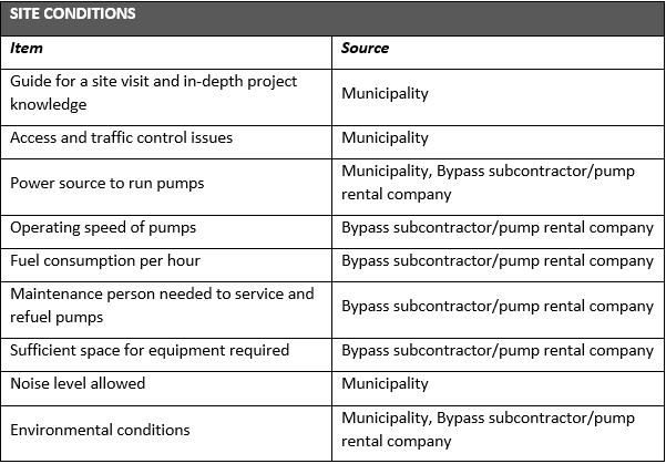
To keep your plans for a sewer bypass on point, here’s a list of the key requirements and where you can get the information to specify them.
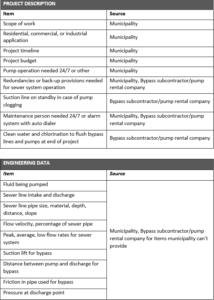

We hope this guide will help you better define the scope and design the solution for sewer bypass projects. But you don’t have to go it alone. It helps to work with a partner that can not only provide high-quality equipment and accessories, but engineering knowledge and installation expertise.
Interested in learning more? Join Sunbelt Rentals for a free webinar with Trenchless Technology on August 15, 2019 at 2 pm EST. Register here
Industry News, trenchless projects
Completion of Excavation a Landmark Event for High-Profile Wastewater Line
 On May 23, 2019, a celebration was in order: The last of six 8.93 m (29.3 ft) diameter EPBs had completed excavation at Lot 4 of Mexico City’s Tύnel Emisor Oriente (TEO), a feat marking the completion of ten years and 62.1 km (38.6 mi) of tunneling. “We are proud of having successfully finished the excavation, despite all the adversities we faced, such as large inflows of water, hydraulic loads and constant changes in geology. We solved these by adapting the excavation mode according to each type of geology found,” said Hector Arturo Carrillo, Machinery Manager for Lot 4 contractor Carso Infraestructura y Construcción (CARSO).
Despite multiple challenges, the operation achieved a project record of 30 m (98 ft) in one day, and a high of 528 m (1,732 ft) in one month. It’s a result that, Carillo says, has much to do with the continuous conveyor system being used for muck removal: “It should be noted that our advance rates were achieved thanks to the great Robbins conveyor design. The tunnel conveyor was composed with elements such as the booster, vertical belt, curve idlers, and advancing tail piece, as well as elements on the surface. Personally, I think it is a great, admirable system that has helped us achieve the TBM’s performance.”
 The breakthrough was the latest and greatest milestone for an urgently needed wastewater project that spanned some of the most difficult geology ever encountered by EPBs. The 10.2 km (6.3 mi) long Lot 4, running from Shaft 17 to Shaft 13 at depths of up to 85 m (280 ft), included sections of basalt rock interspersed with permeable sands with high water pressure. “Our machines had to go through the worst geology, but they were designed for it,” said Roberto Gonzalez Ramirez, General Manager for Robbins Mexico, of the three Robbins EPBs and continuous conveyor systems used on Lots 3, 4, and 5 of the project.
All of the machines were designed for water pressures from 4 to 6 bars, with mixed ground, back-loading cutterheads to tackle variable ground conditions. High pressure, tungsten carbide knife bits could be interchanged with 17-inch diameter carbide disc cutters depending on the geology. Other features included man locks and material locks designed to withstand pressures up to 7 bar, a redesigned bulkhead, and Hardox plates to reinforce the screw conveyors as well as removable wear plates to further strengthen each screw conveyor flight. The rotary union joint was redesigned to improve cutter change times during cutterhead interventions, while a new scraper design offered more impact resistance in mixed ground conditions with rock.
The Lot 4 TBM was assembled in the launch shaft no. 17 and commissioned in August 2012, with the bridge and all the back-up gantries at the surface. Two months later in October 2012, after advancing 150 m (490 ft), the machine and its back-up were completely assembled in the tunnel. One month later, the continuous conveyor system was installed and running.
After 405 m (1,328 ft) of excavation, the presence of rocks, scrapers, parts of the mixing bars and other wear materials in the excavated muck prompted a cutterhead inspection. With high pressure up to 3.5 bars, it was determined that a hyperbaric intervention was necessary, and on June 2nd, 2013 the first hyperbaric intervention through an EPB in a tunnel was performed in Mexico. However, these interventions were done at great cost and proved to be time-consuming. After about 50 hyperbaric interventions the remainder of the project’s interventions were done in open air. “The interventions carried out in atmospheric mode were the biggest challenge. The great influx of water tested the limits, because we were excavating on a decline. In all of these interventions we had to implement a double pumping system, at both the TBM and the shaft,” said Carrillo. Despite the challenges of pumping water at volumes up to 180 l (48 gal) per second and cleaning fines from the tunnel each time the operation was performed, atmospheric interventions were still lower in cost and quicker than those done at hyperbaric pressure.
Even when conditions were tough, Carrillo felt his operation was well-supported by Robbins Field Service: “Robbins were always present giving ideas and contributing all their experience to solve the problems. One of the most recent examples, almost at the end of this project, was where the machine encountered a blockage to the shield and could not move forward. It became necessary to implement the exceptional pressure hydraulic system, reaching a pressure range of 596 bar on 28 thrust cylinders. Robbins personnel helped us during all that time and we were able to get through it.”
Image 1: On May 23, 2019, a Robbins 8.93 m (29.3 ft) diameter EPB completed the final lot of Mexico City’s Tύnel Emisor Oriente (TEO). Capping 62.1 km (38.6 mi) of tunneling.
Image 2: The Robbins crew celebrates the breakthrough of the Robbins EPB at Lot 4 of TEO, after boring 10.2 km in some of the most difficult geology in Mexico.
Visit the Robbins website for more information.
Industry News, trenchless people, trenchless projects
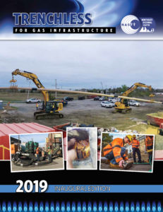 The Northeast Chapter of NASTT has launched a magazine that will be beneficial to the gas industry across the United States.
The inaugural issue of Trenchless for Gas Infrastructure magazine is now available as a complementary download. Trenchless for Gas Infrastructure magazine provides understanding, knowledge and technical innovations regarding the specific application of trenchless technology methods for gas distribution and transmission networks.
Trenchless for Gas Infrastructure is focused on the utility and application of trenchless methods in gas distribution pipeline repair and new construction programs. Content includes articles and case studies demonstrating the benefits of using trenchless technology to repair replace and upgrade gas distribution networks.
The magazine is distributed to senior gas operations and construction executives, engineers and consultants, reaching gas utility LDCs across the US. It is also available as a free download on the NASTT website.
 BRH-Garver Construction LP, a Houston based civil construction contractor pipe jacked 885-linear feet of 66-inch ID Permalok® casing filled with 48-inch carrier lines to convey treated water from the Canal Water Treatment Plant (WTP) for El Paso Water in El Paso, TX. The project risks and rewards existed in equal measure for all stakeholders.